– Code on display
– Error message
– Signal |
Name of Alarm and Cause |
Solution |
– E001
– Input OC
– Orange LED |
Input over-current (photovoltaic generator):
The alarm occurs when the inverter’s input current
exceeds the inverter’s threshold for maximum input current. |
• Check whether the composition of the PV generator enables input current which exceeds the maximum threshold allowed by the inverter and that the configuration of the inputs (independent or in parallel) is carried out correctly.
– If both checks are positive, contact customer assistance |
– E002
– Input OV
– Orange LED |
Input over-voltage (photovoltaic generator):
The alarm is generated when the input voltage (from the PV generator) exceeds the inverter’s threshold of maximum input voltage.
The alarm occurs before reaching the absolute threshold over which the inverter is damaged.
When the inverter’s input voltage exceeds the Over Voltage threshold, the inverter will not start up due to the generation of the alarm. |
• It is necessary to measure the input voltage inside the inverter with a voltmeter.
– If it is higher than the maximum voltage of the operating range, the alarm is genuine and it is necessary to check the configuration of the PV generator. If the voltage has also exceeded the maximum input threshold the inverter could be damaged.
– If it is lower than the maximum voltage of the operating range, the alarm is caused by an internal malfunction and it is necessary to contact customer assistance. |
– E003
– No Parameters
– Orange LED |
DSP initialisation error:
The main microcontroller cannot initialise correctly the
two DSPs (booster stage and inverter stage). The error
is caused by communication problems on the inverter’s
internal bus. |
• Error inside the inverter and cannot be checked externally.
– If the problem (once the inverter has been switched off and back on) persists, contact customer assistance. |
– E004
– Bulk OV
– Orange LED |
“Bulk” over-voltage (DC-DC circuit):
Error inside the inverter. The alarm is raised when the
voltage at the heads of the bulk capacitors exceeds
the Over Voltage threshold (internal unchangeable threshold). |
• The alarm may be triggered by causes external to the inverter:
– An excessive input voltage can be recorded as a condition for bulk over voltage. In this case it is advisable to check the inverter’s
input voltage and should this value be close to the input OV threshold, review the configuration of the photovoltaic generator.
– Excessive grid voltage could cause the bulk voltage to rise in uncontrolled fashion with a consequent protection intervention
and hence generation of the alarm. In these cases the alarm is transitory and the inverter automatically restarts
– The alarm may be triggered by causes inside the inverter and in this case it is necessary to contact customer assistance. |
– E005
– Comm.Error
– Orange LED |
Communication error inside the inverter:
The alarm occurs when there are communication problems between the control devices inside the inverter. |
• Error inside the inverter and cannot be checked externally.
– If the problem (once the inverter has been switched off and back on) persists, contact customer assistance. |
– E006
– Output OC
– Orange LED |
Output over current:
The alarm occurs when the inverter’s output current
exceeds the inverter’s threshold for maximum output
current. |
• Error inside the inverter and cannot be checked externally.
– If the problem (once the inverter has been switched off and back on) persists, contact customer assistance |
– E007
– IGBT Sat
– Orange LED |
Saturation recorded on the IGBT components:
The alarm occurs when one of the inverter’s active devices is in a saturated state. |
Once the error occurs, the inverter tries to return to normal operation.
– Should the error occur sporadically, it may be caused by a brusque transition of the grid voltage or of the input voltage, but is not due to a malfunction by the inverter.
– If the error is connected to an internal breakdown, it will continue to appear and so it is necessary to contact customer assistance. |
– E009
– Internal error
– Orange LED |
Error inside the inverter:
Error inside the inverter |
• Error inside the inverter and cannot be checked externally.
– If the problem (once the inverter has been switched off and back on) persists, contact customer assistance. |
– E010
– Bulk Low
– Orange LED |
Low “Bulk” voltage (DC-DC circuit):
• The alarm may be triggered by causes external to the
inverter: a reduced input voltage on the inverter (just
above the activation voltage) but which is not accompanied by a sufficient availability of power from the photovoltaic generator (typical condition of the stages with limited irradiation) |
– If the error signal occurs sporadically, it may be due to causes external to the inverter (limited irradiation and so limited power availability from the PV generator).
– If the problem occurs systematically also in conditions of high irradiation and with input voltage which is significantly higher than the activation voltage, contact customer assistance. |
– E011
– Ramp Fail
– Orange LED |
Long wait for “Booster” regime to start:
Error internal to inverter relating to start up time for DCDC circuit regime (Booster) |
• Error inside the inverter and cannot be checked externally.
– If the problem (once the inverter has been switched off and back
on) persists, contact customer assistance. |
– E012
– DcDc Fail
– Orange LED |
Error in the “Booster” circuit (DC-DC side) recorded by the “Inverter” circuit (DC-AC side):
Error internal to inverter relating to operation of the DCDC circuit regime (Booster) |
• Error inside the inverter and cannot be checked externally.
– If the problem (once the inverter has been switched off and back
on) persists, contact customer assistance. |
– E013
– Wrong Mode
– Orange LED |
Incorrect configuration of inputs (set in parallel rather than independent):
The alarm is generated solely when the inverter is configured with parallel inputs. In this particular configuration the inverter checks the input voltage of each of the two channels and if the two voltages differ by more than 20Vdc, the alarm is raised. |
• Check that the setting of the “IN MODE” switch is specifically set to “PAR” and that the bridges between the two input channels
have been included.
– If the configuration of the inverter is correct, check that the input strings have the usual number of standard panels of the usual
brand and with the same inclination/orientation.
– If both the configuration of the inverter and the characteristics of the PV generator conform with the specifications, contact customer assistance. |
– E014
– Over Temp.
– Orange LED |
Excessive temperature inside the inverter:
External temperature over 60°C. This parameter also depends on the power which the inverter must supply since the measurement of temperatures is done internally and is influenced by the heat dissipated by the components of the inverter itself |
• Check that the inverter is not exposed to direct sunlight. Wait for the temperatures to which the inverter is exposed to return to the
operating range and for the inverter to cool down.
– If the problem (once the ambient temperature has returned to the range) persists, contact customer assistance. Remember to wait the time needed to allow the inverter to cool down |
– E015
– Bulk Cap Fail
– Orange LED |
Breakdown recorded on the “Bulk” capacitor:
Error inside the inverter relating to a problem in the bulk
capacitors. |
• Error inside the inverter and cannot be checked externally.
– If the problem (once the inverter has been switched off and back
on) persists, contact customer assistance |
– E016
– Inverter Fail
– Orange LED |
Error in the “Inverter” circuit (DC-AC side) recorded by the “Booster” circuit (DC-DC side):
The alarm is generated when a problem is recorded in
the inverter circuit (DC/AC) |
• Error inside the inverter and cannot be checked externally.
– If the problem (once the inverter has been switched off and back
on) persists, contact customer assistance. |
– E017
– Start Timeout
– Orange LED |
Long wait for “Inverter” regime to start up:
Error internal to inverter relating to start-up time for the DC-AC circuit regime (Inverter)
• The alarm may be triggered by causes external to the
inverter: a reduced input voltage on the inverter (just
above the activation voltage) but which is not accompanied by a sufficient availability of power from the photovoltaic generator (typical condition of the stages with limited irradiation) |
– If the error signal occurs sporadically, it may be due to causes external to the inverter (limited irradiation and so limited power
availability from the PV generator).
– If the problem occurs systematically also in conditions of high irradiation and with input voltage which is significantly higher than the activation voltage, contact customer assistance. |
– E018
– Ground Fault
– Red LED |
High leakage current measured on the DC side (photovoltaic generator):
The alarm is generated when, during normal operation
of the inverter, a leakage current to ground is detected in the DC section of the system. It is also possible that the inverter generates the alarm E018 message also due to AC leakage currents connected to the capacitive nature of the photovoltaic generator compared to ground. |
• Measure the insulation resistance using a megohmmeter positioned between the photovoltaic field (positive terminal shortcircuited at the negative pole) compared to ground. The measurement is strongly influenced by the environmental conditions, so must be made under the same conditions in which the error occurred.
– If the value measured is lower than 1 megaohm, a check must be carried out by a technician/installer on the photovoltaic generator to identify and eliminate the problem.
– If the value measured is higher than 1 megaohm and the error signal persists, contact customer assistance. |
– E019
– Ileak sense.fail
– Orange LED |
Failure of test on sensor to measure the leakage current (DC side):
Before connecting to the grid the inverter runs a self-test regarding the sensor for the leakage current. The test is carried out by “forcing”, in the sensor of the leakage current, a current with a known value: the microprocessor compares the value read with the known value.
The error is generated if the comparison between the
read value and the known value during the test does not fall within the allowed tolerance. |
• Error inside the inverter and cannot be checked externally.
By its nature, the alarm only occurs prior to connection to the grid
– If the problem (once the inverter has been switched off and back on) persists, contact customer assistance. |
– E020
– Self Test Error 1
– Orange LED |
Failure of the test on the relay of the “Booster” (DCDC circuit):
Before connecting to the grid the inverter carries out internal tests. One of these tests concerns the correct operation of the booster relay. The test is carried out by “forcing” the switching of the relay and checking its operation.
The error is generated if a problem is found in actioning the relay. |
• Error inside the inverter and cannot be checked externally.
By its nature, the alarm only occurs prior to connection to the grid
– If the problem (once the inverter has been switched off and back on) persists, contact customer assistance. |
– E021
– Self Test Error 2
– Orange LED |
Failure of the test on the inverter’s relay (DC-AC circuit):
Before connecting to the grid the inverter carries out internal tests. One of these tests concerns the correct operation of the inverter relay. The test is carried out by “forcing” the switching of the relay and checking its operation.
The error is generated if a problem is found in actioning the relay. |
• Error inside the inverter and cannot be checked externally.
By its nature, the alarm only occurs prior to connection to the grid
– If the problem (once the inverter has been switched off and back on) persists, contact customer assistance. |
– E022
– Self Test Error 4
– Orange LED |
Timeout of the tests undertaken on the relays inside the inverter:
Execution time for the self-test carried out on the relay
of the DC_AC (inverter) circuit too high. It may indicate a
problem connected to the aforementioned relays |
• Error inside the inverter and cannot be checked externally.
– If the problem (once the inverter has been switched off and back on) persists, contact customer assistance. |
– E023
– DC in error
– Orange LED |
Feeding of continuous current to grid outside of range:
The error is generated if the continuous component of the current supplied to the grid exceeds the threshold of 0.5% of the normal operating current.
In any case the inverter is not blocked due to the E023 error, but tries to reconnect to the grid.
The sporadic repetition of the error is a sign of serious grid distortions or sharp irradiation changes, while systematic repetition of the error signal will indicate a breakdown on the inverter |
Once the error occurs, the inverter tries to return to normal operation.
– Should the error occur sporadically, it may be caused by a brusque
transition of the grid voltage or of the input voltage, but is
not due to a malfunction by the inverter.
– If the error is connected to an internal breakdown, it will continue to appear and so it is necessary to contact customer assistance. |
– E024
– Internal error
– Orange LED |
Error inside the inverter:
Error inside the inverter |
• Error inside the inverter and cannot be checked externally.
– If the problem (once the inverter has been switched off and back on) persists, contact customer assistance. |
– E025*
– Riso Low
– Orange LED |
*not visualised on display
Low value of insulation resistance:
Before connecting to the grid the inverter measures the insulation resistance of the PV generator compared to ground. Should the measurement of the insulation resistance be below 1Mohm, the inverter does not connect to the grid and shows the “Riso Low” error. The causes may be:
– PV panel(s) damaged;
– Junction box(es) of the panels not correctly sealed, so as to permit infiltration by water and/or humidity;
– Problems in connections between panels (not perfectly fit);
– Poor quality of cable joints;
– Presence in the DC section of unsuitable or damaged overvoltage surge arresters outside the inverter (reduced ignition voltage compared to the characteristics of the strings of the PV generator);
– Presence of humidity inside any junction box |
• Measure the insulation resistance using a megohmmeter positioned in the photovoltaic field (positive terminal short-circuited at the negative pole) compared to ground. The measurement is strongly influenced by the environmental conditions, so must be made under the same conditions in which the error occurred.
– If the value measured is lower than 1 megaohm, a check must be carried out by a technician/installer on the photovoltaic generator to identify and eliminate the problem.
– If the value measured is higher than 1 megaohm and the error signal persists, contact customer assistance.
For more information on ABB Aurora inverter RISO Low error messages, click here. |
– E026
– Vref Error
– Orange LED |
Internal reference voltage outside of range:
Wrong measurement of reference voltage inside inverter |
• Error inside the inverter and cannot be checked externally.
– If the problem (once the inverter has been switched off and back on) persists, contact customer assistance. |
– E027
– Error Meas V
– Orange LED |
Grid voltage outside of range:
Error in the internal measurement of grid voltage (set by law) in order to have a redundant measurement (2 measurements on the same parameter made by two different circuits) |
• Error inside the inverter and cannot be checked externally.
– If the problem (once the inverter has been switched off and back on) persists, contact customer assistance. |
– E028
– Error Meas F
– Orange LED |
Grid frequency outside of range:
Error in the internal measurement of grid frequency (set by law) in order to have a redundant measurement (2 measurements on the same parameter made by two different circuits) |
• Error inside the inverter and cannot be checked externally.
– If the problem (once the inverter has been switched off and back on) persists, contact customer assistance. |
– E029
– Mid Bulk OV
– Orange LED |
Internal over voltage on the measurement of the “Mid bulk”:
Error internal to the inverter (only triphase models) |
• Error inside the inverter and cannot be checked externally.
– If the problem (once the inverter has been switched off and back on) persists, contact customer assistance. |
– E030
– Error Meas Ileak
– Orange LED |
High leakage current (DC side):
Error in the internal measurement (made when the inverter is grid connected) of the leakage current of the DC side (PV generator) compared to ground (set by law) in order to have a redundant measurement (2 measurements on the same parameter made by two different circuits) |
• Error inside the inverter and cannot be checked externally.
– If the problem (once the inverter has been switched off and back on) persists, contact customer assistance. |
– E031
– Error Read V
– Orange LED |
Output relay damaged:
Measurement of internal voltage on heads of the output relay outside of range. There is too great a difference in voltage between the input and output of the grid connection relay. |
• Error inside the inverter and cannot be checked externally.
– If the problem (once the inverter has been switched off and back on) persists, contact customer assistance.
For more information on ABB Aurora inverter E031 error messages, click here. |
– E032
– Error Read I
– Orange LED |
Imbalanced output currents:
Measurement of the unbalance in the output voltage
(made across the three phases) outside of range (only
in triphase models) |
• Error inside the inverter and cannot be checked externally.
– If the problem (once the inverter has been switched off and back on) persists, contact customer assistance. |
– E033
– UTH
– Orange LED |
Low ambient temperature:
Temperature outside the inverter below -25°C |
• Wait for the temperatures to which the inverter is exposed to return to the operating range.
– If the problem persists, contact customer assistance. Remember to wait the time needed to allow the inverter to warm up |
– E034
– Interlock fail
– Orange LED |
“IGBT” circuitry not ready:
Error inside the inverter |
• Error inside the inverter and cannot be checked externally.
– If the problem (once the inverter has been switched off and back on) persists, contact customer assistance. |
– E035*
– Remote Off
– Orange LED |
*not visualised on display
Inverter awaiting “remote ON” command:
The inverter has been switched off remotely (remote OFF) and remains awaiting the signal which will switch it back on (Remote ON) |
• Switch back on the inverter remotely. If the unit does not switch back on, disable the remote off/on function and switch the equipment off completely and subsequently switch it back on.
– If the problem (once the Remote ON/OFF function from the display has been reactivated) persists, contact customer assistance. |
– E036
– Vout Avg error
– Orange LED |
Average of the measurements of grid voltage outside of range:
The average value of the grid voltage (sampled every 10 minutes) does not fall within the permitted ranges. The grid voltage in the point connected to the inverter is too high. This may be caused by too high a grid impedance.
In the final stage of the timeout, the inverter limits the power to check whether the grid voltage has stabilised into regular parameters. If this does not happen, the inverter disconnects from the grid |
• Check the grid voltage in the connection point to the inverter.
– If the grid voltage differs from the range due to the conditions of the distribution grid, ask the operator to adjust the grid voltage.
If the operator authorises a change to the inverter’s parameters, agree the new limits with customer assistance |
– E037
– Riso Low
– Red LED |
Low value of the insulation resistance (only with the “Amorphous” mode activated):
This error can occur only should the “Amorphous” mode be on. This function is on only in inverters equipped with a grounding kit and serves to monitor the voltage at the heads of the grounding resistance. The error occurs when the voltage at the heads of the resistance connected between ground and the pole of the photovoltaic generator exceeds 30V for more than 30 minutes or 120V for more than one second. |
• Check for the presence and correct contact between the two terminals of the grounding resistance installed inside the inverter
• Measure the insulation resistance using a megohmmeter positioned in the photovoltaic field (positive terminal short-circuited at the negative pole) compared to ground. The measurement is strongly influenced by the environmental conditions, so must be made under the same conditions in which the error occurred.
– If the value measured is lower than 1 megaohm, a check must be carried out by a technician/installer on the photovoltaic generator to identify and eliminate the problem.
– If the value measured is higher than 1 megaohm and the error signal persists, contact customer assistance |
E046
– String self test fail
– No LED |
Error during the automatic check of the string voltages (only in models with the “fuse-control” board):
In some inverter models it is possible to carry out the check test of the polarity of the strings connected to the input (e.g.:TRIO-20.0/27.6kW).
This error signal occurs when, during the test stage, an inverted string is recorded |
• Section the inverter and check the polarity of the string(s) which the inverter has recorded as inverted.
– Once all the strings have been correctly connected, activate the system once again; the inverter will once again check the correct polarity of the string inputs at the end of which it will carry out the checks for the grid connection.
– If the problem (once the inverter has been switched off and back on) persists, contact customer assistance. |
E049
– AC FF Error
– Orange LED |
Error in the “AC feed-forward” circuit:
Error inside the inverter |
• Error inside the inverter and cannot be checked externally.
– If the problem (once the inverter has been switched off and back on) persists, contact customer assistance. |
E056
– Over Temp. (from external box)
– Orange LED |
Input voltage (Vin) higher than booster voltage (Vbulk):
The error occurs if the input voltage exceeds the Bulk
voltage (voltage on the DC-DC circuit inside the inverter |
• It is necessary to measure the input voltage inside the inverter with a voltmeter.
– If it is higher than the maximum voltage of the operating range, the alarm is genuine and it is necessary to check the configuration of the PV generator. If the voltage has also exceeded the maximum input threshold the inverter could be damaged.
– If it is lower than the maximum voltage of the operating range, the alarm is caused by an internal malfunction and it is necessary to contact customer assistance |
E058
– Pin vs Pout check error
– Orange LED |
Error in the check of Pin vs Pout:
The error occurs if the difference between the measured value of input power and that of output power is greater than the limit imposed internally to the inverter. |
• Error inside the inverter and cannot be checked externally.
– If the problem (once the inverter has been switched off and back on) persists, contact customer assistance |
 The Delta Solivia range of solar inverters can develop a number of different faults and when a fault is present an error message will be displayed on the screen and usually one or a number of the LED’s be lit. The below is a list of error messages, explanations on the error or fault and a list of possible actions to take to resolve the issue.
  For further details check out the Delta Solivia Solar Inverter manual which can be downloaded below. The Delta Solivia came with a 10 year warranty against defects so if the instructions above hasn’t rectified the error the best thing to do is to contact the company who installed your inverter originally. If your inverter is outside the warranty period you will need to talk to a solar accredited electrican. If you’re in the Gold Coast or Brisbane area contact Gold Coast Power Solutions here and our solar power experts will be able to provide you with further assistance.
 The CMS 1500 and CMS 2000 solar inverters can develop a number of different faults and when a fault is present an error message will be displayed on the screen and usually the fault light would be lit. The below is a list of error messages, explanations on the error of fault and a list of possible actions to take to resolve the issue.
 For a full reference of this information you can check the CMS-2000 Solar Inverter manual under the Inverter Status and Troubleshooting sections. Unfortunately the manufacturer of the CMS-2000 Solar Inverter has been placed in receivership so the owners of this inverter are left without a warranty. If you are in the Gold Coast or Brisbane area
 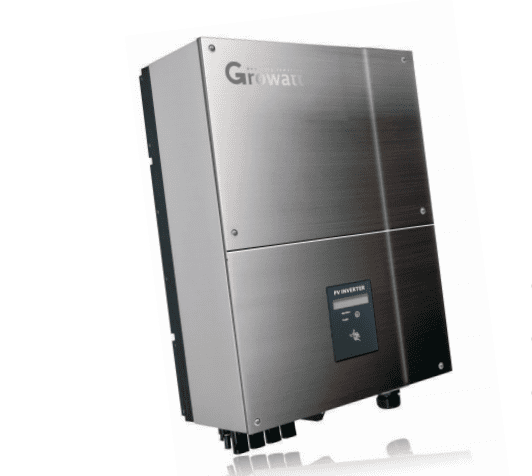 For a Chinese-manufactured brand, Growatt MTL solar inverter can perform better than its Chinese counterparts, add to that that it is cheaper than European inverters on the market.
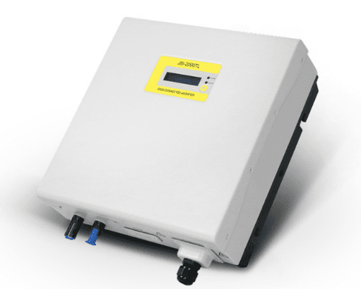 JFY JSI Solar Inverter is a Chinese-manufactured brand so it can be expected that it is way cheaper compared to European inverters on the market. Several factors may affect an inverter’s performance which may result in failures.
 JFY SunTwins Solar Inverter has a dual-string series of inverters which aims to provide a much better experience.
 If your KLNE SunTeams Solar Inverter does not operate normally, you will observe that a fault will be showing up on its display screen and the LED will be lit at the same time. We have put together a list of causes and remedy for these faults from


 The proper installation of a Macsolar Solar Inverter would prolong its life. However, should there be any internal issues with the inverter this will be detected by the device and cause the Fault light to be displayed permanently. If the red light is on or if there is a green light without the yellow Run light a manual shutdown procedure is recommended.
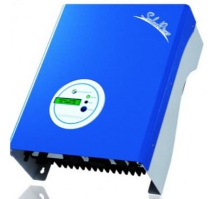 When a fault occurs on your Samil SolarRiver Inverter it is important to check the warning or fault message. This will provide information on the next steps to take.
 In the event of a problem with the SEA Orion Solar Inverter, the red fault LED will turn on, the green power light is off and the LCD will display a message identifying the cause of the fault. Take note of the fault to diagnose the problem in your SEA Orion Solar Inverter.
 A Sharp JH1600e Solar Inverter would usually show an error or event code to specify a fault. We listed these codes from
  When your SolarKing Solar Inverter does not operate normally, you will observe that a fault will be shown up on its display screen and the red fault light will be lit at the same time.
 SolaX Solar Inverter is a hybrid inverter that allows you to use your solar power at night after you charge your battery. It also directs power to any appliances operating throughout the day while storing unused power in the battery. You can also monitor its real-time performance through your iPhone or Android phone with the SolarMAN app.
 Sungrow is now the world’s largest manufacturer of solar inverters with an inverter range that has proven to be quite reliable. Its Sungrow KTL-M Solar Inverter has a 10-year warranty on parts and 5 years on labor is offered at a reasonable price.
 Sungrow KTL-D solar inverter is a good option if you happen to be on a tight budget. This Chinese solar inverter brand offers a standard 5-year warranty on parts and labor. The inverter also allows monitoring of real-time performance through your iPhone or Android phone with the SolarInfo Home App.
 Xantrex solar inverters were originally made by a Canadian company but have since been bought out by Schneider Electric. A few years ago, they discontinued the Xantrex model and introduced the Context range to replace it. So when a Xantrex solar inverter fails under warranty, it is replaced with the new Schneider.
 The ABB Aurora Power-One Inverter has a wide range of inverters. This can be an advantage because this almost meets any customer requirement but which can also be a disadvantage since this can be confusing. This light-weight inverter is compatible with monitoring systems and does a good job once it’s up and running.
 If your Fronius GALVO, PRIMO or SYMO solar inverter is displaying a STATE 567 message on the screen we have some good news and bad news for you;